
How about presenting CFD analysis from the virtual space?
Think about the money you can save during the design stage rather than later at the project handover or even worse during the liability period. The painful process of troubleshooting the given infrastructure. Altering, and modifying the given infrastructure cost can be significant:
- Cost of delay in production or science research
- Cost of altering the given infrastructure
- Cost of engineering hours is like a money furnace for the consulting firms
- Cost of the future projects for the consulting firm if the reputation may be in the line
- Cost of unforeseen resource involvement from all parties
- And the list can go on…
Versus
- Little investment – at the early stage of the design, conceptual or schematic stages – in CFD analysis to find out potential design shortcomings as early as possible while still able to move walls, and furniture that impacts user’s process planning.
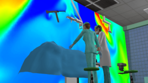
- A virtual walkthrough helps the engineers effortlessly convey the engineering challenges during User workshops without diving into some nerdy engineering details
- User workshops often get focus on architectural planning – understandably for the User process planning – and the infrastructure may get neglected. This might be a reason why some infrastructure troubles don’t surface till it is in actual use.
- Virtual CFD walkthrough can simply give an insight for both Users and architects for planning that supports the infrastructure design
- We should not forget that the infrastructure design is the one that will make these facilities function. Laboratories, cleanrooms, and production facilities are infrastructure-heavy.
How to visualize airflow patterns?
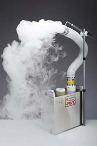
The traditional way is the use of foggers for airflow visualization in cleanrooms, laboratories, and healthcare facilities. Needless to mention this happens at the commissioning stage of the project before handing over to the client. This is still important as it is the final verification before all system goes live.
A little more details about this verification method. If you are familiar with it, you can skip it to the next paragraph.
Fog generators produce a high-density fog by quenching steam with liquid nitrogen to produce small (~3µm in diameter), pure water droplets suspended in a nitrogen carrier gas. The resulting fog is highly visible and truly non-contaminating. The droplets leave no measurable residues when they evaporate in the cleanroom air. These foggers can meet the most stringent demands of modern semiconductor and pharmaceutical cleanrooms. The non-contaminating nature of these fog generators make them suitable for use in an operating cleanroom without interrupting ongoing production or other activities taking place in the cleanroom.
Visualize and track airflow faithfully in cleanrooms to determine the airflow trajectory for:
- Troubleshooting
- Photographic or video recording of airflow patterns
- Flow balancing
- Optimizing equipment location to minimize contaminant transport to critical areas
- Finding unsuspected particulate and gaseous contaminant sources
- Finding routes of air infiltration into the cleanroom
- Visualizing standing vortices in laminar-flow cleanrooms
- Studying wake flow behind objects in vertical laminar flow and mixed-flow cleanrooms
- Operator training on good contamination control practices
Computational fluid dynamic tools have been around for a while…
What is CFD?
Computational Fluid Dynamic creates a digital simulation that visualizes the flow of fluids in the way they are affected by objects.
Imagine you can peek into the future and see how your designed system is going to work before anything solid has been built. This gives you the ability to adjust and perfect your system even if you are still in the design phase.
This is better for your state of mind and can also save a lot of money.
CFD is used to find out how hotspots, air velocities, and temperature levels work in a specific room. Although deployable in any space, it is usually applied in complex situations where you do not exactly know how certain properties will behave.
CFD provides solid proof that you will meet the design requirements.
CFD tools are brilliant however undeniably nerdy tools that can be demanding to convey the infrastructure design challenges especially when airtime given to the engineer is rather short.
Animated airflow visualization
Have a peek into the full version of this animated airflow analysis. (click on the text highlighted in red)
Animated airflow visualization from virtual space helps to get the messages through with ease.
During the design stage, the design team and users can explore multiple test fit-outs without any risk and the need for hefty investment in the construction.
The time spent peaking into a virtual airflow pattern is insignificant to what a potential project handover delay may be caused by troubleshooting the system.
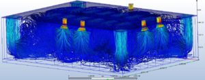
This animated airflow is based on actual data from a CFD software. There are “infinity” numbers of airflow splines/data points in the CFD analysis, which as you see in the above image may not be easy to see through the forest of data and perhaps even harder to grasp. However, we can pick point interest of areas, and animate those splines. We can comfortably walk in the virtual space and observe the most influential air patterns. It is also an excellent tool for design verification, client presentation, or simply any design demonstration.
The color of the splines in the video presentation represents the airflow velocity. Which helps to easily filter where the velocity may exceed the permissible range. The moving speed of the airflow splines in this demonstration does not represent the actual airflow velocity.
The above CFD image is a screenshot from a CFD tool and represents the actual data animated in the linked video.
If you made it this far, thanks for your time and for reading this post. Look forward to reading your comments. Please share this post if you liked the content and get in touch to learn more about animated CFDs.